

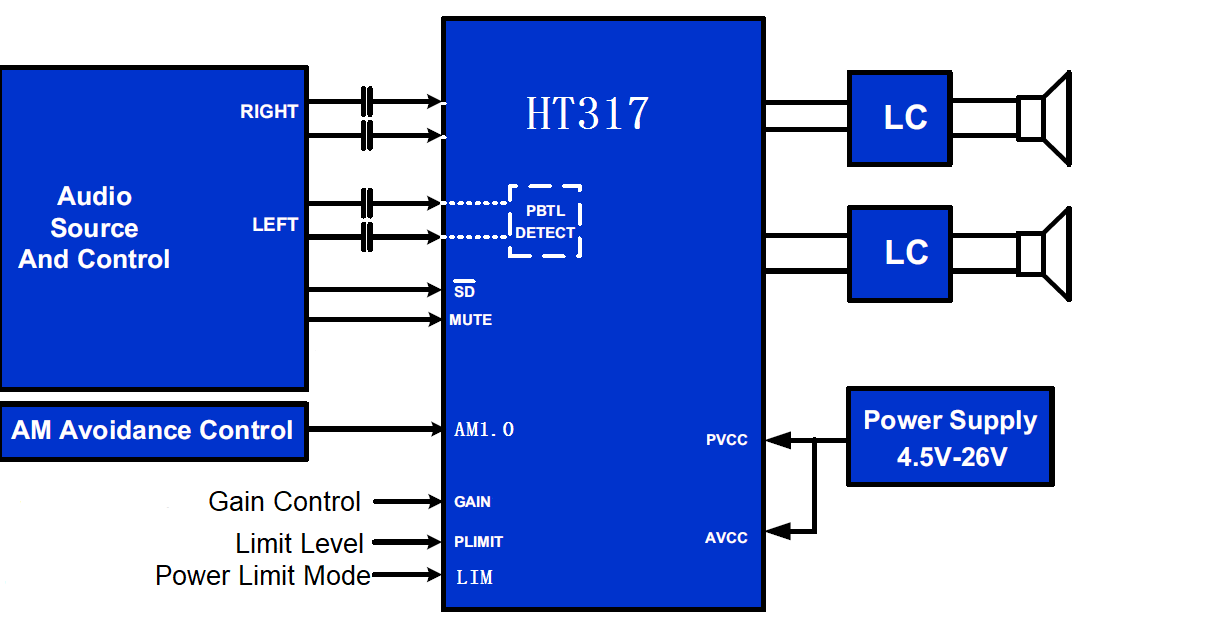
HT317 is a stereo efficient, Class-D audio amplifier for driving speakers up to 75W/4 ? in mono PBTL. It can also deliver 2×30W/8Ω power in stereo BTL.
HT317 features 2 different power limit functions. One is power clipper (PCLP), which can clip the output voltage under a preset level; another one is AGC which can limit the output music under a preset level without clipping.
Thermal Foldback (TFB) function is designed to protect HT317 from excessive die temperature in case of the device being operated beyond the recommended temperature or power, or with a weak thermal system, without shutting the device down.
Multiple switching Frequency is selectable for HT317 to avoid AM interferences.
HT317 is fully protected against faults with Overvoltage, Undervoltage, Overtemperature, DC-detect, and Overcurrent protection. Faults can be reported to the processor to prevent devices from being damaged
FEATURE
| APPLICATIONS
|

TERMINAL FUNCTION
Pin No. | Name | I/O | Description |
1 | \SD/FAULT | I | SD/FAULT, multi function pin. When pulled down, place the speaker amplifier in shutdown mode. |
2 | INA+ | I | Positive input terminal for A channel |
3 | INA- | I | Negative input terminal for A channel |
4 | PLIMT | I | Set the maximum output voltage before clipping (Limiter Level) |
5 | GVDD | O | Voltage regulator derived from PVDD supply, connect 1uF to GND (NOTE: This pin is provided as a connection point for filtering capacitors |
6 | GAIN | I | Adjust the gain of the speaker amplifier |
7 | LIM | I | Select the mode of Digital Output Clipper or AGC |
8 | GGND | G | Ground for gate drive circuitry (this terminal should be connected to the system ground) |
9 | INB- | I | Negative input terminal for B channel |
10 | INB+ | I | Positive input terminal for B channel |
11 | AM0 | I | AM Avoidance Frequency Selection |
12 | AM1 | I | AM Avoidance Frequency Selection |
13 | MUTE | I | Mute control terminal, the amplifier is muted when it is pulled high |
14 | AVDD | P | Analog power supply |
15,16,17 | PVDD | P | Power Supply for amplifier drivers of B channel |
18 | BSB+ | BST | Connection point for the OUTB+ bootstrap capacitor, which is used to create a power supply for the high-side gate drive for OUTB+ |
19 | OUTB+ | O | Positive pin for differential speaker amplifier output B |
20 | OUTB- | O | Negative pin for differential speaker amplifier output B |
21 | BSB- | BST | Connection point for the OUTB- bootstrap capacitor, which is used to create a power supply for the high-side gate drive for OUTB- |
22 | BSA- | BST | Connection point for the OUTA- bootstrap capacitor, which is used to create a power supply for the high-side gate drive for OUTA- |
23 | OUTA- | O | Negative pin for differential speaker amplifier output A |
24 | OUTA+ | O | Positive pin for differential speaker amplifier output A |
25 | BSA+ | BST | Connection point for the OUTA+ bootstrap capacitor, which is used to create a power supply for the high-side gate drive for OUTA |
26,27,28 | PVDD | P | Power Supply for amplifier drivers of A channel |
PAD | PGND | G | Power ground, make sure connect it to the system ground |
I: Input; O: Output; G: Ground; P: Power; BST: Boot Strap